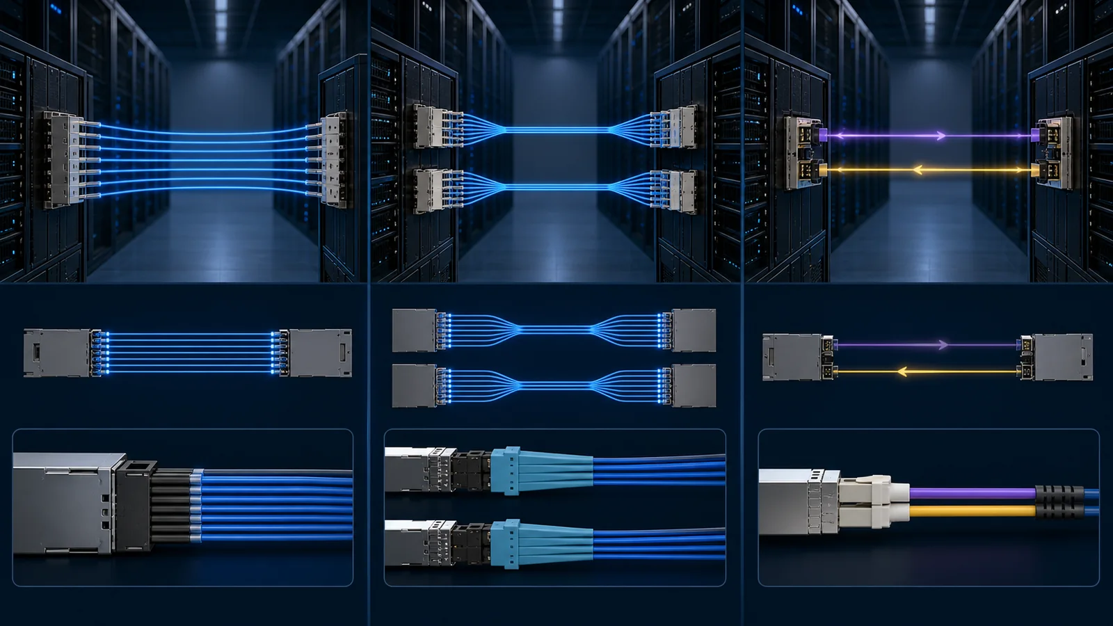
An 800G module name can describe a line rate without telling the buyer how the optical lanes are organized. That missing detail changes the connector, fiber count, patching plan, breakout options, fault domain and the evidence required before an order is approved. DR8, dual DR4 and dual FR4 may all appear in an 800G quotation, yet they can represent very different physical links.
The first discipline is terminology. IEEE 802.3df-2024 defines formal Ethernet PMDs including 800GBASE-DR8, 800GBASE-DR4 and 800GBASE-FR4. Phrases such as 2xDR4, dual DR4 or 2xFR4 are often vendor architecture descriptions for two logical 400G optical engines in one 800G-class module. They are useful descriptions when backed by a data sheet, but they are not automatically the names of separate IEEE PMDs. Procurement should therefore record both the supplier's exact model description and the standards clause or interoperability target it claims.
For a buyer, the practical comparison is straightforward. DR8 normally exposes eight parallel single-mode transmit lanes and eight receive lanes. A dual-DR4 implementation divides the module into two four-lane optical groups, often to support two 400G endpoints or a two-way breakout. A dual-FR4 implementation can use two wavelength-multiplexed four-wavelength engines, commonly presenting two duplex optical interfaces. The label alone is not enough: the data sheet must disclose the connector, lane map, reach, fiber type and supported host mode.
Quick comparison
| Buyer question | 800G DR8 architecture | Dual DR4 architecture | Dual FR4 architecture |
|---|---|---|---|
| Optical organization | Eight parallel single-mode lanes in each direction | Two groups of four parallel single-mode lanes | Two groups of four wavelengths carried over duplex single-mode fiber |
| Typical external fiber concept | Parallel-fiber interface | Two parallel-fiber groups or a defined dual-port interface | Two duplex optical paths, subject to the actual connector |
| Natural procurement use | One 800G parallel link | One module serving two defined 400G optical groups or a vendor-specific aggregate mode | One module serving two wavelength-multiplexed 400G optical groups |
| Breakout potential | Depends on host mode, module design and lane access | Often central to the design, but must be confirmed for the exact module and host | Often two logical optical engines, but electrical breakout and management still require proof |
| Main cabling risk | Wrong fiber count, polarity or parallel connector | Wrong branch mapping or assuming every dual-port device breaks out the same way | Treating duplex connectors as interchangeable without checking wavelength, reach and loss budget |
| Evidence required | PMD target, lane map, connector, fiber assembly and host support | Two logical ports, branch identity, endpoint PMD and host channelization | Each engine's PMD, wavelength plan, connector, path loss and host channelization |
This table is an architecture guide, not a compatibility matrix. Individual products may depart from the common pattern, especially where a proprietary connector, twin-port OSFP shell, internal gearbox or special host profile is used.
Start with the endpoint, not the module headline
The buying process should begin with a port-to-port record. Identify the exact host at End A and End B, the port or port group, required line rate, network protocol, software release and whether the intended service is one 800G link or two 400G links. If the design is a breakout, record the branch endpoints individually.
A module advertised as 800G dual DR4 does not prove that a switch can expose two independently managed 400G ports through that cage. The host ASIC, port profile and software must support the requested channelization. Conversely, a host may support 2x400G electrically while a candidate optical module presents an aggregate optical interface that cannot be separated in the intended manner. The valid combination is established only when the host mode and the module lane map agree.
Ask the supplier for a controlled diagram containing:
- host electrical lanes and their grouping;
- module electrical interface and any gearbox function;
- optical transmit and receive lane numbering;
- external connector and keying;
- branch identifier for each logical link;
- supported aggregate and breakout modes;
- required FEC and auto-negotiation behavior;
- management-page method for selecting or reporting each data path.
Without this diagram, the buyer is forced to infer architecture from a short title. That is how an apparently correct 800G part reaches site with the wrong fiber assembly or an unusable branch configuration.
DR8: parallel optics and fiber-plant consequences
DR8 uses parallel single-mode transmission. In an eight-lane arrangement, the optical interface carries eight independent transmit lanes and eight receive lanes. The fiber plant must preserve lane order and polarity end to end. A parallel connector can make the rack design compact, but it also makes cassette, trunk, harness and inspection choices part of the optical specification.
The central buyer questions are not limited to nominal reach. Confirm the exact connector family and polish, whether the module interface is pinned or unpinned, the required mating assembly, lane polarity, maximum channel insertion loss, reflection constraints and the permitted number of connection points. A generic statement such as "MPO compatible" is inadequate because MPO is a connector family rather than a complete channel definition.
DR8 can be valuable when the installed plant is designed for parallel optics or when the architecture must expose lower-rate parallel lanes. It can be costly when the site is standardized on duplex LC infrastructure and would need new trunks, panels and inspection equipment. The transceiver price is therefore only one component of the decision.
For acceptance, inspect and clean the full parallel end face, then test the channel in a way that preserves per-lane information. An aggregate link-up result can hide a weak lane that is being rescued by FEC. Record pre-FEC indicators, corrected and uncorrectable events, lane-level optical power where available, and the actual fiber assembly serial or lot.
Dual DR4: two optical groups require explicit branch control
A dual-DR4 design commonly packages two four-lane parallel optical engines. That can align well with 2x400G breakout projects, particularly in dense AI fabrics. The engineering benefit is not merely that eight lanes have been divided by two. Each group becomes a logical asset that needs a stable identity from the host port through the cable plant to the far-end port.
The purchase order should name Branch A and Branch B. The installation drawing should show which connector, fiber group and far-end endpoint belongs to each branch. If a twin-port OSFP or dual optical connector is involved, document physical orientation rather than relying on "left" and "right" language that may reverse when viewed from the rear of the rack.
Do not assume that a dual-DR4 product supports every combination of aggregate 800G and 2x400G operation. Some products are designed around a specific switch or adapter family. Some rely on an electrical lane arrangement that the target host does not offer. Others may expose management and alarms differently for each data path. Obtain a host-qualified model list or run a controlled sample test on the exact port group and software release.
The far-end optics must also be defined. If each branch is intended to connect to a 400G DR4 endpoint, confirm the endpoint's formal PMD, reach and connector. Similar lane counts do not prove optical interoperability. Transmitter wavelength, power, receiver limits, FEC and timing behavior remain part of the link.
Dual FR4: wavelength multiplexing changes the fiber decision
FR4 uses four optical wavelengths over a duplex single-mode path. A dual-FR4 module can therefore represent two wavelength-multiplexed optical engines in one mechanical module. Compared with a parallel DR architecture, this can reduce external fiber count and align with duplex LC-oriented cabling, but it introduces a different optical budget and a different service boundary.
Each FR4 engine combines and separates wavelengths internally. Procurement should obtain the specified reach, transmitter and receiver limits, maximum path loss, connector type, reflection limits and operating-temperature range. If the product is marketed as 2xFR4, confirm whether each engine follows an IEEE PMD, an MSA profile or a vendor-specific target. Do not convert a vendor headline into a standards claim.
Two duplex links can be simpler for technicians familiar with LC patching, yet branch identity still matters. Label the two optical engines, maintain A-to-B mapping through patch panels and ensure that the host exposes the intended electrical channelization. A duplex connector does not remove the need for a port map.
FR4 is not automatically the better answer because it uses fewer fibers. Wavelength-multiplexed optics can have different module power, thermal behavior and cost. Parallel optics may provide a more direct breakout path in a plant already built around parallel trunks. The correct comparison includes the installed cabling, expected migrations and spare strategy rather than only the first link.
Reach names must not replace a link budget
DR and FR names communicate a PMD class, but they do not approve a real route. Build a channel loss record using the actual fiber length, connector pairs, cassettes, splices and an engineering margin. Compare that figure with the governing specification and the exact product data sheet.
Avoid three common shortcuts. First, do not use transmitter power minus receiver sensitivity as the only available budget without checking how the specification defines stressed sensitivity and penalties. Second, do not assume a 500 m or 2 km name means every route below that length will pass; contamination and reflection can fail a short link. Third, do not reuse a loss budget from a duplex FR path for a parallel DR path without accounting for different connectors and channel definitions.
The link-budget guide explains how to structure the calculation. For this architecture decision, add fiber count and branch mapping to the same record so optical and operational risks are reviewed together.
Host, FEC and management evidence
At 800G, optical link approval cannot be separated from host behavior. Record the requested FEC mode, the mode actually active, lane or data-path state, corrected codewords, uncorrectable codewords, pre-FEC BER where supported, link-down events and module alarms. A clean link light is a starting point, not a full acceptance result.
For dual-engine modules, verify whether telemetry is available per data path. Confirm how the host reports temperature and optical power, how it identifies each branch, and what happens when one branch is disconnected or degraded. Test recovery after a port flap, module reinsert and controlled host reboot. If software upgrades are part of the deployment, repeat the critical tests on the intended release.
The module memory map should match the declared management standard and product revision. Save the raw identification and diagnostics output rather than only a screenshot. This creates a traceable baseline for future lot changes or RMA investigation.
Cabling and operations cost model
A robust total-cost comparison includes at least five layers:
- Module cost: candidate optics, approved second source and operational spares.
- Fiber plant: trunks, harnesses, panels, cassettes, cleaning tools and inspection capability.
- Deployment labor: branch labeling, polarity verification and acceptance testing.
- Failure isolation: whether a fault can be isolated to a lane, branch, module or fiber assembly without replacing the whole link.
- Migration value: whether the fiber and endpoints support the next planned port mode.
DR8 may be economically strong in a greenfield parallel plant but expensive in a duplex brownfield site. Dual DR4 can simplify a 2x400G fabric when branch mapping is controlled, while becoming risky if technicians cannot identify the two paths. Dual FR4 can reduce fiber count while increasing dependence on the module's wavelength-multiplexed engines. There is no universal lowest-cost architecture.
Sample-validation plan
Use samples from the intended production revision and retain their labels, serials and data sheets. Test more than one physical host port and, where practical, more than one sample. A useful matrix includes:
- aggregate and breakout modes actually required;
- both branch orientations for dual-engine modules;
- planned fiber assemblies and worst-case connection count;
- cold start, warm restart and module reinsert;
- sustained traffic at the intended packet and load profile;
- pre-FEC trend, corrected and uncorrectable codewords;
- module temperature and relevant optical diagnostics;
- one planned failure, such as removing a branch or inserting a known-loss element;
- recovery behavior and alarm clearing;
- a comparison against the approved reference optic where available.
Do not invent a universal BER threshold. Use the standard, host-vendor guidance and project acceptance criteria for the exact link. Record counter intervals and clear counters deliberately so rates are not confused with lifetime totals.
RFQ fields that prevent the wrong purchase
An evidence-based request for quotation should include:
- exact hosts, hardware revisions, software and port numbers at both ends;
- one 800G service or two 400G services;
- required aggregate and breakout modes;
- formal PMD or interoperability target for every optical endpoint;
- connector, fiber type, route length, measured loss and patching topology;
- required branch mapping and labels;
- target FEC and management behavior;
- maximum module power, airflow and ambient conditions;
- required data-sheet, host-support and sample-test evidence;
- production revision control, lot traceability and change notification;
- quantity, delivery schedule and spare policy.
The supplier should return exceptions against this record. A quote that repeats "800G DR8" or "2xFR4" without a lane map and evidence boundary is not ready for technical approval.
Decision summary
Choose DR8 when a parallel single-mode architecture matches the host, plant and breakout plan. Choose a dual-DR4 implementation when two defined four-lane optical groups align with the required 2x400G topology and the host supports the exact mode. Choose dual FR4 when two wavelength-multiplexed duplex paths fit the plant and operating model. In every case, the module title is only the beginning.
Keep the form-factor decision separate by using the 800G OSFP versus QSFP-DD guide. Use the compatibility checklist to document the exact host and software boundary. For a project review, send the endpoint, port mode, fiber map and candidate data sheets; PhotonVerge can return an evidence-gap matrix without representing an untested combination as qualified for deployment.
Primary sources
- IEEE P802.3df Task Force - records approval of IEEE Std 802.3df-2024 and provides the authoritative project history.
- IEEE 802.3df optical PMD definitions and comment resolution - public technical material distinguishing DR8, DR8-2 and related PMD terminology.
- IEEE 802.3df baseline proposal for 800GbE optical lanes - lane-count context for 800G DR8, DR4 and FR4 architectures.
- NVIDIA LinkX cables and transceivers guide - vendor-specific examples of DR8, 2xDR4 and 2xFR4 terminology; not a universal interoperability guarantee.
- NVIDIA LinkX 100G-PAM4 product-line overview - current vendor context for parallel and dual-port optical products.