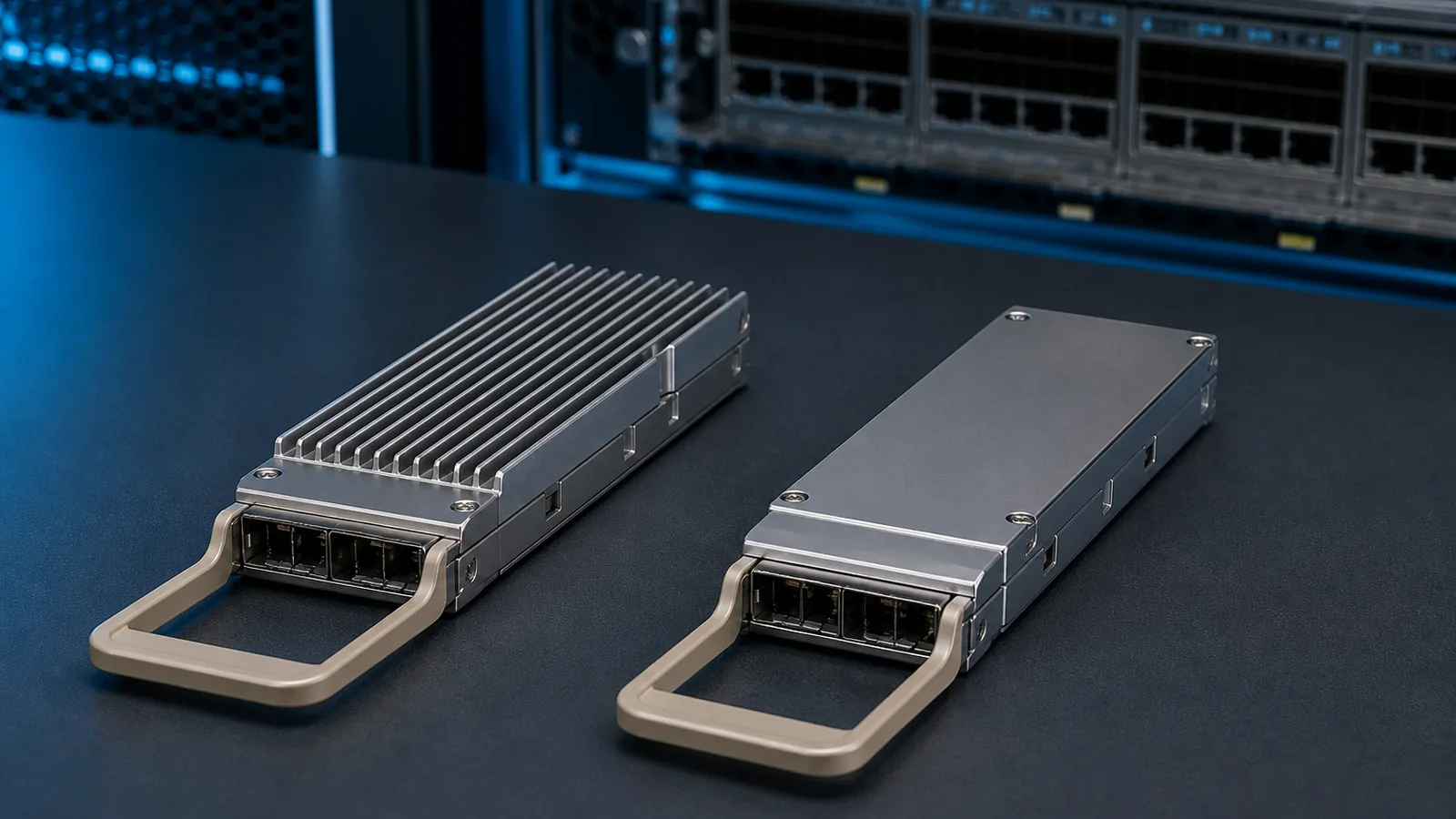
An OSFP can have the right speed, optical reach, connector and protocol yet still be the wrong item for the equipment in front of you. The failure may be obvious—the module will not seat correctly—or subtle: the plug fits, but the host and module do not form the cooling arrangement that the equipment vendor qualified.
For a buyer, “finned top” and “flat top” are therefore not cosmetic options. They describe two different ways of completing the thermal interface. A standard OSFP may carry an integrated heat sink on the module. An OSFP-RHS module presents a flat upper surface and relies on a riding heat sink provided by the host cage. NVIDIA documentation often calls these IHS and RHS variants respectively. The correct choice begins with the exact endpoint, not with a photograph or a speed label.
This guide is for 400G and 800G OSFP procurement in NVIDIA-oriented AI and HPC fabrics. It explains a repeatable review method. It does not declare that every switch uses fins or that every adapter uses a flat top. Product generations, air- and liquid-cooling designs, single- and twin-port implementations, and supported part numbers differ. The current equipment manual and validated-component list remain the controlling sources.
The first distinction: which side owns the heat sink?
The OSFP MSA describes the mechanical module and host interface. Its public material distinguishes the standard OSFP, which has an integrated heat sink, from OSFP-RHS, which requires a separate riding heat sink. That distinction answers a practical question: when the module is inserted, are the cooling fins part of the removable module, or are they part of the equipment cage?
| Buyer-facing term | Physical arrangement | What must be confirmed before ordering |
|---|---|---|
| Finned top / IHS in the cited NVIDIA examples | Heat-sink structure is integrated into the removable OSFP shell | The host cage is designed to receive that exact integrated shell, including its height and mechanical details; do not generalize this label mapping beyond the named platform documentation |
| Flat top / RHS | The OSFP shell has a flat thermal surface; a host-side riding heat sink contacts it | The host actually provides the intended riding heat sink and applies it to the correct module geometry |
| Open or closed integrated heat sink | Variants within the integrated-heat-sink family | The equipment and module documents specify the allowed construction; “finned” alone may not be a sufficient ordering description |
-FLT or similar vendor suffix | A manufacturer-specific ordering clue, not a universal standard code | The suffix must be checked against the exact vendor ordering table and revision |
Neither arrangement is inherently better. An integrated heat sink can be appropriate for a densely packed air-cooled switch designed around that shell. A riding heat sink can be appropriate where the chassis provides pressure, airflow or a liquid-cooled interface above the cage. The wrong conclusion is to treat the flatter part as a lower-power version or the finned part as a universally better-cooled version. Thermal performance belongs to the module-plus-cage-plus-chassis system.
Start with an endpoint pair, not an optic description
A usable purchase line must name both ends of the link. “800G OSFP, 500 metres” is not enough. An NDR switch, a ConnectX adapter and a DGX network module can expose OSFP-looking interfaces while requiring different shell, port and breakout arrangements.
NVIDIA’s current NDR cabling guide gives a concrete example. Quantum-2 QM9700 switch cages use a tall finned OSFP connector and implement two logical NDR ports in one physical twin-port connector. The same guide describes flat single-port OSFP connectors for adapters and QSFP112 connectors for space-constrained DPU connections. NVIDIA’s LinkX portfolio material further distinguishes flat-top twin-port OSFP variants used with certain DGX H100/H200 internal riding-heat-sink cages and liquid-cooled applications. Those are product-generation examples, not a permanent rule for every NVIDIA platform.
Before asking for a quote, build an endpoint record with these fields:
- Equipment manufacturer and full chassis or system model.
- Line card, adapter, DPU or internal network-module model where applicable.
- Physical port or cage designation from the equipment manual.
- Whether the port is single-port or twin-port at the OSFP connector.
- Required link speed and port mode at each end.
- Air-cooled or liquid-cooled chassis configuration, including the documented heat-sink arrangement.
- Operating software and relevant adapter or switch firmware.
- Required optical PMD or cable technology, reach, fiber type and connector.
- Candidate manufacturer part number, including every suffix.
This record prevents a common purchasing error: copying a part description from a similar topology and assuming that the shell designation follows the speed. It does not. Two links running the same nominal data rate may terminate in different equipment and need different ends.
Single-port and twin-port OSFP are a separate decision
Finned versus flat is only one axis. Port topology is another. NVIDIA’s NDR architecture uses an eight-lane twin-port OSFP at certain switches to expose two independent 400G-class links through one physical connector. A 400G single-port OSFP uses four high-speed lanes. The shells may share the OSFP family name, but a buyer cannot exchange them merely because the aggregate numbers appear to match.
This becomes especially important with split assemblies. A switch-side twin-port OSFP may fan out to two flat-top OSFP ends, two QSFP112 ends, or another documented combination. The cable is not just “OSFP to OSFP.” Its electrical lanes, logical ports, end-A/end-B shells and host roles are part of the product definition.
Use a simple end map in the BOM:
| BOM field | End A | End B |
|---|---|---|
| Equipment and port | Exact switch/system and cage | Exact adapter/DPU/system and cage |
| Connector role | Twin-port or single-port | Twin-port or single-port |
| Shell/cooling | IHS finned, RHS flat, or documented variant | IHS finned, RHS flat, or documented variant |
| Logical links | Number and speed enabled | Number and speed expected |
| Lane/breakout map | Host port mode | Host port mode |
| Media | DAC, ACC/AEC, AOC, or transceiver plus fiber | Matching assembly/interface |
If a supplier quote does not make the two ends distinguishable, the line is not ready for approval. A photograph of one connector end is not a substitute for the end map.
A six-gate purchasing review
Gate 1: Verify the cage from the host document
Use the equipment installation guide, supported-cable list or product specification—not an image search—to identify the cage. Record whether its heat sink is integrated with the removable module or rides on a flat module surface. If the system is liquid-cooled, identify the exact chassis option; a liquid-cooled deployment should not be inferred from the product family name.
For DGX H100/H200 systems, NVIDIA instructs buyers to consult the firmware-specific list of validated and supported cables and adapters. This is a useful discipline for any platform: hardware appearance is not the final support boundary, and firmware may change the recognized component set or port behavior.
Gate 2: Resolve the manufacturer’s terminology
Translate marketing descriptions into physical facts. Ask whether “flat top” means OSFP-RHS in that vendor’s document, whether the unit is single-port or twin-port, and whether a suffix such as -FLT is part of the orderable part number. Keep the source document title, revision and access date in the purchase record.
Do not normalize different suppliers’ suffixes into one invented coding scheme. A reseller description may omit a suffix, shorten a legacy part number, or combine a product name with an internal SKU. The manufacturer’s current ordering table is the reference for the original item; a compatible alternative must state which physical implementation it is intended to replace without claiming automatic equivalence.
Gate 3: Match port topology and protocol
Confirm how many logical ports sit behind the physical connector and how the host is configured. Record InfiniBand or Ethernet mode where the platform supports both, along with the desired NDR, NDR200 or Ethernet speed. If a breakout is involved, show the lane and port mapping rather than relying on “1-to-2” in the description.
The shell cannot repair a topology mismatch. A correctly cooled single-port module is still wrong for a twin-port switch cage if the platform documentation does not support that use.
Gate 4: Match the optical or cable interface
After mechanical and electrical fit, review the media. For a transceiver, confirm the optical PMD, wavelength plan, fiber type, connector polish and reach. For an integrated cable, confirm the technology, length, bend route and exact connector at both ends. An MPO/APC interface is not interchangeable with an MPO/UPC interface because both are called MPO. Color can assist receiving inspection but should never replace the drawing and part number.
Gate 5: Check power and cooling as installed
Obtain the module’s maximum power and operating case-temperature range from the model-specific data sheet. Then check the host’s supported power class, airflow direction, fan policy, adjacent-port loading and ambient conditions. A typical-power figure is not a thermal qualification, and a chassis-level port limit is not evidence that every module will remain within its case-temperature range.
For high-density rows, ask the platform owner to define the worst credible population pattern. A single sample in an otherwise empty switch can pass while a fully populated row runs closer to the thermal boundary. If the host provides module temperature and alarms, retain those observations with the traffic load, ambient reading and test duration. Do not turn a short lab observation into a lifetime guarantee.
Gate 6: Confirm software, coding and support evidence
The host may identify the module, apply power limits, select an application code or restrict unsupported parts. Record the software and firmware versions used for approval. Ask for the module identity readout and relevant management-interface information. A physical fit and link-up event are necessary observations, but they do not prove long-duration error performance, support across other software releases or contractual warranty coverage.
Receiving inspection should catch the mismatch before power-on
Mechanical errors are cheapest to correct before the module reaches a live system. Receiving staff need a visual and documentary check that is specific enough to distinguish the intended ends.
First compare the purchase order, packing label and module label. Preserve the manufacturer part number, supplier SKU, serial number, hardware revision and any -FLT or equivalent suffix. Photograph the top and connector end without removing labels. For asymmetric breakout cables, label end A and every end B branch before the assembly is routed.
Next inspect the shell. Confirm the expected integrated fins or flat thermal surface, the single- or twin-port construction, pull-tab orientation and key mechanical features against the approved drawing. Do not force a module into a cage to “see whether it fits.” A mismatch should be quarantined and reviewed against the host and vendor documents.
Finally, inspect the optical interface and protective caps. Record MPO/APC versus MPO/UPC or the applicable duplex connector, and follow the approved inspection-and-cleaning procedure before connection. The top style does not tell you the fiber polish, lane map or optical PMD.
The receiving record should result in one of three statuses: matches the approved order line; documentation incomplete; or physical mismatch. “Looks similar” is not a status.
Thermal acceptance is an operating test, not a label check
After receiving inspection, validate the candidate in a controlled system. Begin with the known-good host baseline and capture the host model, port, software, firmware, port mode, FEC, module identity and chassis cooling state. Insert the module according to the equipment procedure and confirm proper latch engagement and, for RHS implementations, correct contact with the host-side heat sink.
Run representative traffic for an agreed duration. Capture module temperature, voltage, optical power or other available telemetry, plus link events and corrected/uncorrectable error indicators. Observe the system at a realistic inlet temperature and port population where practical. If the platform exposes only limited telemetry, record the missing fields rather than filling them with supplier assumptions.
The conclusion must remain narrow. A defensible statement is that a named sample operated in a named host, software release, port mode, cooling condition and test window. It is not evidence that every unit, every adjacent-port population or every firmware release will behave identically. Production approval also needs lot traceability and an agreement about change notification.
Five mistakes that repeatedly create OSFP returns
Ordering by photo. Product images are often representative and may show the other shell option. Approve the orderable code and drawing.
Treating finned and flat as universal switch/server categories. They are host-implementation choices. Use the exact generation and cage documentation.
Ignoring single-port versus twin-port architecture. Aggregate speed can hide two independent links and an asymmetric breakout.
Dropping suffixes during quotation. A shortened part number can erase the only visible clue that distinguishes the flat-top variant. Preserve the complete manufacturer code and supplier cross-reference.
Accepting link-up as thermal proof. Link-up says little about a loaded chassis, error trends, airflow margin or production-lot consistency.
Lock the approved construction into the purchase record
The final purchase line should retain every attribute that made the sample acceptable: complete manufacturer part number, IHS or RHS construction, single- or twin-port topology, optical interface, connector, temperature class, maximum power, coding profile, hardware revision and any approved equivalent. Attach the host models and the evidence revision used for approval. A description such as “800G OSFP compatible” is too broad to control a repeat order.
Also define which changes require notice and re-review. A new shell or heat-transfer surface, altered maximum power, different optical engine, revised module firmware, changed label suffix or substitute bill of materials may affect mechanical fit, thermal behavior or host recognition even when the sales description stays the same. The supplier should not silently map an approved order line to a “functionally equivalent” construction. If substitution is commercially necessary, quarantine the new revision until documentation review and the agreed regression checks are complete.
This record makes the receiving inspection repeatable and protects future replenishment. It also gives engineering and purchasing the same definition of “approved,” which is essential when a field issue must be traced to a particular lot or revision.
What a buyer should send for a model review
For a useful review, send one line per link type rather than a list of module names. Include the two endpoint models and ports, air- or liquid-cooled configuration, a cage photo or equipment drawing if available, software and firmware, intended speed and breakout mode, required reach, fiber/connector details, candidate manufacturer part number, quantity and deployment schedule.
The requested output should be equally specific: proposed orderable item; shell and cooling arrangement at each end; single/twin-port mapping; media and connector; model-specific source documents; open compatibility or thermal questions; and the sample-acceptance plan. Price and lead time should attach to that reviewed configuration, not to a shortened description.
Use the OSFP versus QSFP-DD guide only if the cage family itself is still undecided; this article begins after OSFP has been selected. Once the shell and topology are resolved, the sample validation plan provides the separate acceptance workflow.
PhotonVerge can use the inputs above to prepare a candidate cross-reference and evidence checklist. The review should be treated as conditional until the exact host documentation and, where required, a controlled sample test are complete. Send the endpoint and cooling record for review.
Primary sources
All dynamic web sources below were last checked on 11 August 2026. A current host manual and support record still control any future model claim.
- OSFP MSA, “OSFP Module Specification Rev. 5.22,” published 14 August 2025, and the current OSFP/OSFP-XD specification index: https://osfpmsa.org/specification.html
- OSFP MSA, public FAQ on standard OSFP integrated heat sinks and OSFP-RHS: https://osfpmsa.org/index.html
- NVIDIA, “LinkX 100G-PAM4 Product Line Overview,” including twin-port IHS and RHS host-use boundaries: https://docs.nvidia.com/networking/display/400g100gpam4ovdev/linkx-100g-pam4-product-line-overview
- NVIDIA DGX SuperPOD, “Cabling Data Centers Design Guide — NDR Components”: https://docs.nvidia.com/dgx-superpod/design-guide-cabling-data-centers/latest/ndr-components.html
- NVIDIA, “LinkX 400GbE + NDR Combo Main Portfolio (100G-PAM4),” Rev. October 7, 2024: https://docs.nvidia.com/linkx-400gbe-ndr-combo-main-portfolio-100g-pam4.pdf
- NVIDIA DGX H100/H200 User Guide, network cables and adapter support boundary: https://docs.nvidia.com/dgx/dgxh100-user-guide/introduction-to-dgxh100.html