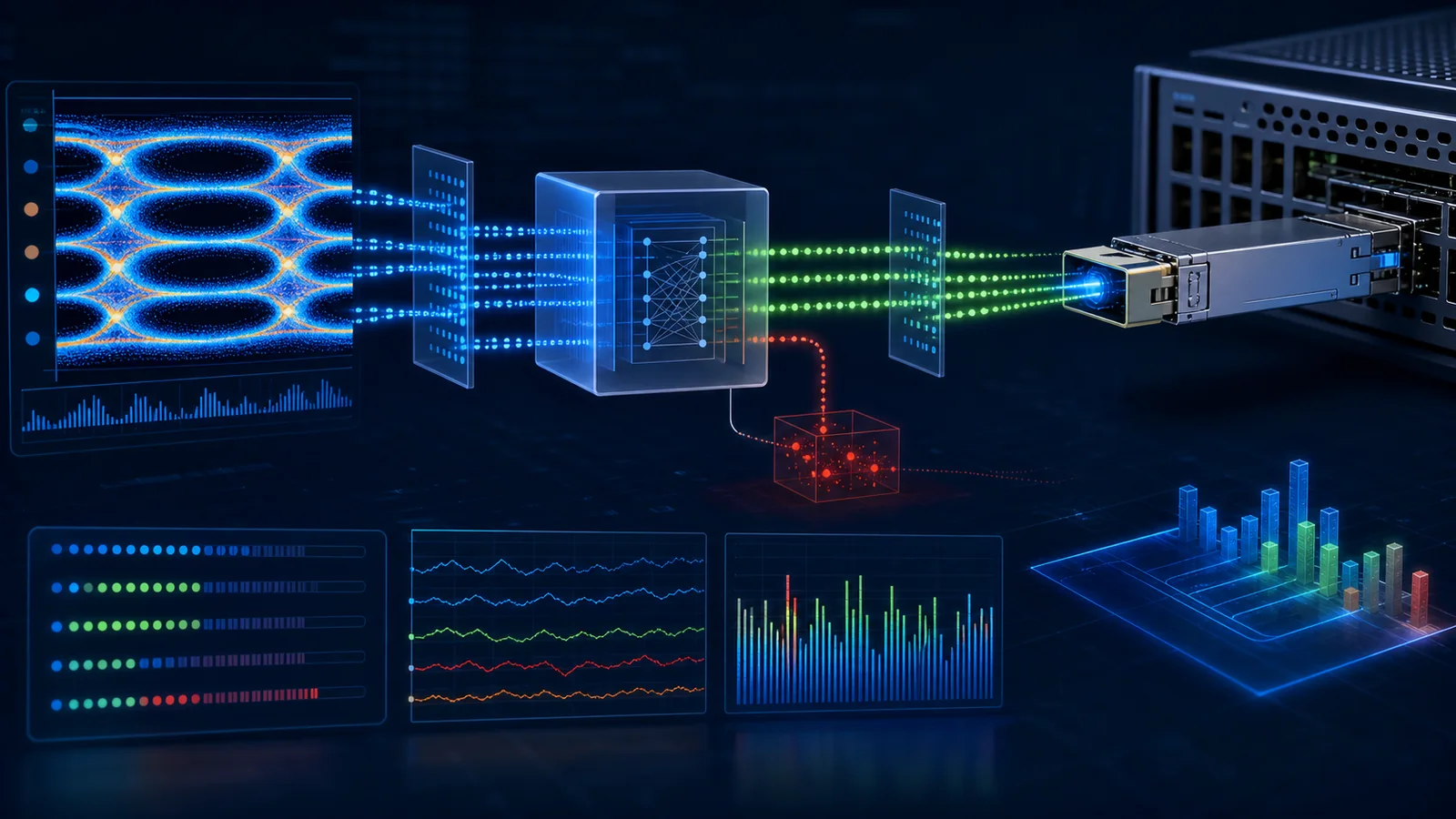
A high-speed optical link can remain up while forward error correction is working hard. That is the purpose of FEC: correct a bounded number of transmission errors before they become packet loss. The operational mistake is to treat every corrected event as a failed link, or to treat a green link state and zero packet loss as proof of healthy margin.
Pre-FEC BER, corrected codewords, uncorrectable codewords, symbol-error histograms, CRC errors and link-down events describe different stages of the same system. They must be read together, over a controlled time interval, with the actual FEC mode, traffic condition and endpoint configuration recorded. A single lifetime counter copied from a switch is not a diagnosis.
This guide explains a disciplined interpretation workflow for PAM4 links. It does not prescribe a universal pass/fail threshold. The governing Ethernet or InfiniBand specification, host-vendor documentation, project design margin and exact platform implementation remain controlling.
The minimum counter model
| Signal or counter | What it can tell you | What it cannot prove by itself |
|---|---|---|
| Pre-FEC BER or raw BER estimate | Error activity before FEC; useful for margin trending | That packets are being lost, or that a universal threshold has been crossed |
| Corrected codewords or corrected bits | FEC is detecting and repairing errors | That the link is failing; correction is normal within the code's capability |
| Uncorrectable codewords or frames | FEC could not repair one or more codewords | Root cause; the fault may be optics, fiber, electrical channel, configuration or transient behavior |
| Post-FEC BER / effective errors | Residual error behavior after correction, when implemented | A complete service-impact picture without CRC, drops and traffic context |
| FEC histogram | Distribution of symbol corrections per codeword; valuable for margin shape | Direct comparison across unrelated ASICs or software without matching definitions |
| Lane-level raw errors | Whether degradation is concentrated on one lane | Whether the fault is on the transmitter, receiver, connector or fiber without controlled swaps |
| CRC/FCS errors and drops | Errors or loss reaching higher layers | The original physical impairment without lower-layer evidence |
| Link-down events | Loss of link state or recovery instability | Whether the trigger was signal, software, operator action or remote endpoint |
The hierarchy matters. Corrected errors occur below the packet layer. Uncorrectable events can propagate upward, but their relationship to CRC and traffic loss depends on implementation and protocol. Always preserve counter names and platform definitions.
Why PAM4 links depend on FEC
PAM4 encodes two bits per symbol using four amplitude levels. Compared with a two-level NRZ signal, the separation between adjacent levels is smaller, so the receiver has less amplitude margin for noise and distortion. Modern high-speed links use equalization and FEC as part of the designed channel, not as optional repairs for a defective product.
This changes the meaning of "errors." A healthy PAM4 link can show corrected FEC activity. The engineering question is whether that activity is stable and consistent with the expected margin, not whether the corrected counter is exactly zero. A rapidly rising correction rate, a lane that is much worse than its peers, or any uncorrectable activity under normal conditions deserves investigation.
FEC must also match at both endpoints. Record the requested mode and the active mode. A port can fail to link or behave unpredictably if the hosts use incompatible FEC or auto-negotiation settings. Do not analyze optical power until configuration is confirmed.
Establish a measurement window
Before comparing counters, create a clean interval:
- capture the current port configuration and active FEC;
- record uptime, link state and last-change time;
- save the lifetime counters;
- clear counters only if the operating policy permits;
- note the exact start time;
- run defined traffic or observe a defined production interval;
- capture the same counters at the end;
- calculate deltas and rates using the real elapsed time.
Never compare a five-minute counter delta with a six-month lifetime total. Do not clear the only copy of incident evidence before saving it. If a platform reports pre-FEC BER directly, determine whether it is instantaneous, averaged, minimum, maximum or accumulated over a vendor-defined window.
Traffic matters. Some defects appear only under full bidirectional load, certain lane mappings, bursts or temperature conditions. An idle link and a stressed link are different tests. Record packet profile and offered load when they are part of acceptance.
Read corrected codewords as a trend
Corrected codewords show that FEC is performing its intended function. An absolute count has limited meaning without time and traffic. Convert the observation into a rate or compare deltas across identical intervals.
Three patterns are especially useful:
- Stable low activity: the count rises slowly and consistently, with no uncorrectable events or higher-layer errors. This may be normal for the platform and channel.
- Step change: the correction rate increases after a cable move, temperature change, software update or component replacement. The event correlation is more informative than the absolute count.
- Accelerating trend: correction activity rises over time under unchanged traffic, especially during warm-up. This can indicate declining margin, contamination, thermal behavior or a marginal electrical channel.
Compare peer links carefully. Ports with the same host, optic, fiber topology, software and traffic provide a useful local baseline. A different module technology or route is not a clean control. Do not convert a fleet percentile into a standards limit without engineering justification.
Uncorrectable events require immediate context
An uncorrectable FEC event means the received error pattern exceeded the correction capability for that codeword or frame. It is more serious than ordinary corrected activity, but it still does not identify root cause.
When an uncorrectable count appears, preserve:
- exact timestamp and counter delta;
- active FEC, port speed and breakout mode;
- CRC/FCS, symbol and packet-drop counters;
- link state and link-down history;
- per-lane raw error data where supported;
- module alarms, temperature and optical power;
- remote-end counters from the same interval;
- traffic event, reboot, cable movement or maintenance activity;
- host and module software/firmware revisions.
Correlate the direction. Errors reported by End A's receiver relate to the optical or electrical path transmitting from End B toward End A. This sounds obvious, but incident records frequently replace the wrong transmitter because the team follows the port where the error counter is displayed without tracing signal direction.
If the event is isolated, repeat under controlled traffic and monitor. If it recurs, move one variable at a time. A mass swap of modules, fibers and ports may restore service but destroys root-cause evidence.
Use lane-level data to narrow the fault
Many platforms expose raw error or BER estimates per lane. A single weak lane can point toward a contaminated or damaged parallel-fiber position, one transmitter/receiver channel, a connector issue or an electrical lane impairment. Uniform degradation across all lanes may suggest common power, temperature, fiber loss, configuration or host-channel issues.
Lane numbering must be mapped. Host electrical lane 0 may not correspond to the first visible fiber in the way a technician expects, especially through gearboxes, breakouts or polarity methods. Use the module and cable lane map before acting on a lane-specific counter.
For parallel optics, inspect and clean the complete ferrule, then compare lane data before and after. For wavelength-multiplexed optics, lane telemetry may refer to electrical lanes, optical wavelengths or data paths depending on the implementation. Preserve the vendor's counter definition.
Do not declare a transmitter defective from receive-side lane data alone. Swap against a known-good fiber path, port or module in a controlled sequence and document which direction changes.
FEC histograms reveal margin shape
A FEC histogram can show how many symbol corrections occur within codewords. Juniper describes this as a more detailed view of link quality and exposes corrected, uncorrected, pre-FEC BER and histogram information on supported systems. The value of the histogram is not a single magic bin; it is the distribution and how it changes.
A distribution concentrated at low correction counts may represent comfortable operation. A shift toward codewords requiring many corrections can indicate reduced margin even before uncorrectable events appear. Compare the same platform, FEC mode, software and observation window.
Histograms are implementation-specific. Bin definitions and collection intervals can differ. Store the raw command output and platform documentation with the test record. A graph copied into a report without those definitions is not independently auditable.
Separate optical and electrical evidence
The link includes two host electrical channels, two module electrical interfaces, two optical transmit/receive paths and the fiber plant. FEC sees the resulting errors but does not say where they originated.
Optical evidence includes transmit power, receive power, alarms, channel loss, connector condition and wavelength-specific data. Electrical evidence includes host SerDes state, equalization, cable loss, lane training and module-host interface behavior. Temperature and firmware can affect both.
Use a controlled substitution plan:
- confirm configuration at both ends;
- inspect and clean accessible optical connectors;
- replace the fiber assembly with a known-good equivalent;
- move to a known-good port group if permitted;
- replace one module, keeping direction and serial traceability;
- compare against an approved reference pair;
- repeat after warm-up and under the same traffic.
Stop when the evidence isolates the variable. Do not continue swapping merely to produce a green result.
Optical power is not the same as margin
DOM receive power within a displayed range does not prove the link has adequate margin. DOM accuracy has tolerances, and receiver performance also depends on signal quality, penalties and the applicable PMD. Conversely, a receive-power reading near an alarm threshold may be a real warning or a poorly interpreted vendor threshold.
Use the exact module specification and link-budget method. Record path loss, connection count and engineering margin. Compare power trends with FEC trends: if receive power falls while corrections rise, the optical path becomes a stronger hypothesis. If power is stable but one electrical lane degrades after a software change, investigate host and interface behavior.
The DOM/DDM report guide explains how to distinguish raw telemetry from a complete validation report. Do not use DOM screenshots as the only approval evidence.
Temperature and warm-up behavior
Collect counters and temperature from cold start through thermal stabilization. A link that is clean for two minutes and degrades after forty minutes is not represented by a short acceptance test. Populate a realistic number of neighboring ports and preserve airflow conditions.
Trend module temperature, correction rate and optical power on the same timeline. Correlation does not automatically prove causation, but it guides the next controlled test. If moving the module to a cooler, known-good port removes the trend, repeat enough times to separate temperature from port-specific behavior.
Do not invent a universal module temperature limit. Use the product's specified case or sensor limits and the host's thermal policy. Report whether the value is module internal temperature, case temperature or ambient inlet.
Software and firmware regressions
Host software can change FEC defaults, counter calculations, lane mapping, module initialization or alarm handling. Module firmware can also change behavior where updates are supported. A link approved on one release should not be assumed identical after a major upgrade.
Before an upgrade, save:
- port configuration and active FEC;
- module identity and firmware;
- baseline pre-FEC and FEC counters under controlled traffic;
- DOM values and temperatures;
- breakout and lane mapping;
- known alarms or accepted exceptions.
After the upgrade, repeat the same observation. If counter names or definitions changed, document that before comparing figures. A rollback decision should be based on reproducible degradation, not merely a different display format.
Acceptance criteria should be layered
A strong acceptance plan uses multiple gates:
- Configuration gate: expected speed, FEC, breakout and protocol are active.
- Link-state gate: link initializes and recovers through required restart scenarios.
- Traffic gate: defined bidirectional traffic completes without prohibited loss.
- FEC gate: corrected behavior is within project criteria and no prohibited uncorrectable events occur.
- Trend gate: pre-FEC and lane indicators remain stable through the defined interval and temperature range.
- Optical gate: measured path and diagnostics are consistent with the product specification.
- Operational gate: alarms, identification and evidence collection work on the intended software.
Project criteria should cite their origin: formal standard, host-vendor limit, product data sheet, instrument method or approved fleet baseline. If no defensible threshold exists, state that the sample is being compared with an approved reference under identical conditions rather than inventing a number.
Common interpretation errors
"Any corrected errors mean the optic is bad." Incorrect. FEC exists to correct errors. Investigate rate, trend, distribution and system context.
"No packet loss means the link has margin." Incorrect. FEC may be masking rising raw errors. Trend lower-layer evidence.
"Receive power is normal, so the fiber is good." Incomplete. Power does not capture every optical penalty, connector defect or lane-specific problem.
"The failing side is the port displaying errors." Not necessarily. Receive errors at one end relate to the opposite transmit direction and the intervening path.
"Clear counters and see if it happens again." Save them first. Clearing without evidence destroys the incident baseline.
"One threshold applies to every 400G and 800G platform." Incorrect. FEC, PMD, ASIC, measurement window and vendor implementation matter.
Evidence package for supplier escalation
Send a compact, reproducible package:
- topology and signal direction;
- exact host models, ports and software;
- module models, serials, revisions and firmware;
- fiber assembly identity and measured path loss;
- active speed, breakout and FEC;
- start/end timestamps and counter deltas;
- pre-FEC, corrected, uncorrectable, CRC and link-event data;
- lane-level data and histogram where available;
- DOM, temperature and alarms;
- traffic method and duration;
- controlled swaps already performed;
- known-good reference result;
- photos of labeling and connector condition where useful.
Do not send only a cropped screenshot. Raw command output preserves counter names and context. Remove credentials and unrelated customer information before sharing.
Decision summary
Read PAM4 link health as a hierarchy. Confirm configuration first. Use pre-FEC BER and corrected counters as trends, treat uncorrectable events as serious evidence requiring context, use lane and histogram data to narrow margin, and correlate lower-layer behavior with optical power, temperature, CRC, traffic and link events.
For broader fault isolation, use the optical link and RMA triage guide. For procurement testing, use the sample-validation plan. To review a real incident, send the host pair, active FEC, time window and sanitized raw counters. PhotonVerge can organize an evidence-gap review without claiming that one undocumented threshold applies to every platform.
Primary sources
- Juniper Optics Pre-FEC BER Rate - platform-vendor explanation of pre-FEC BER, corrected/uncorrected codewords and FEC histograms.
- Juniper interface feature documentation - release-specific counter and 800G feature context.
- Juniper monitor interface error reference - definitions for corrected errors, pre-FEC BER and uncorrected errors.
- NVIDIA UFM telemetry counter reference - current vendor-specific examples of pre-FEC samples, lane raw BER, corrected bits and effective errors.
- NVIDIA secondary telemetry fields - definitions connecting raw BER, effective BER, FEC and uncorrectable codeword counters; version-specific.