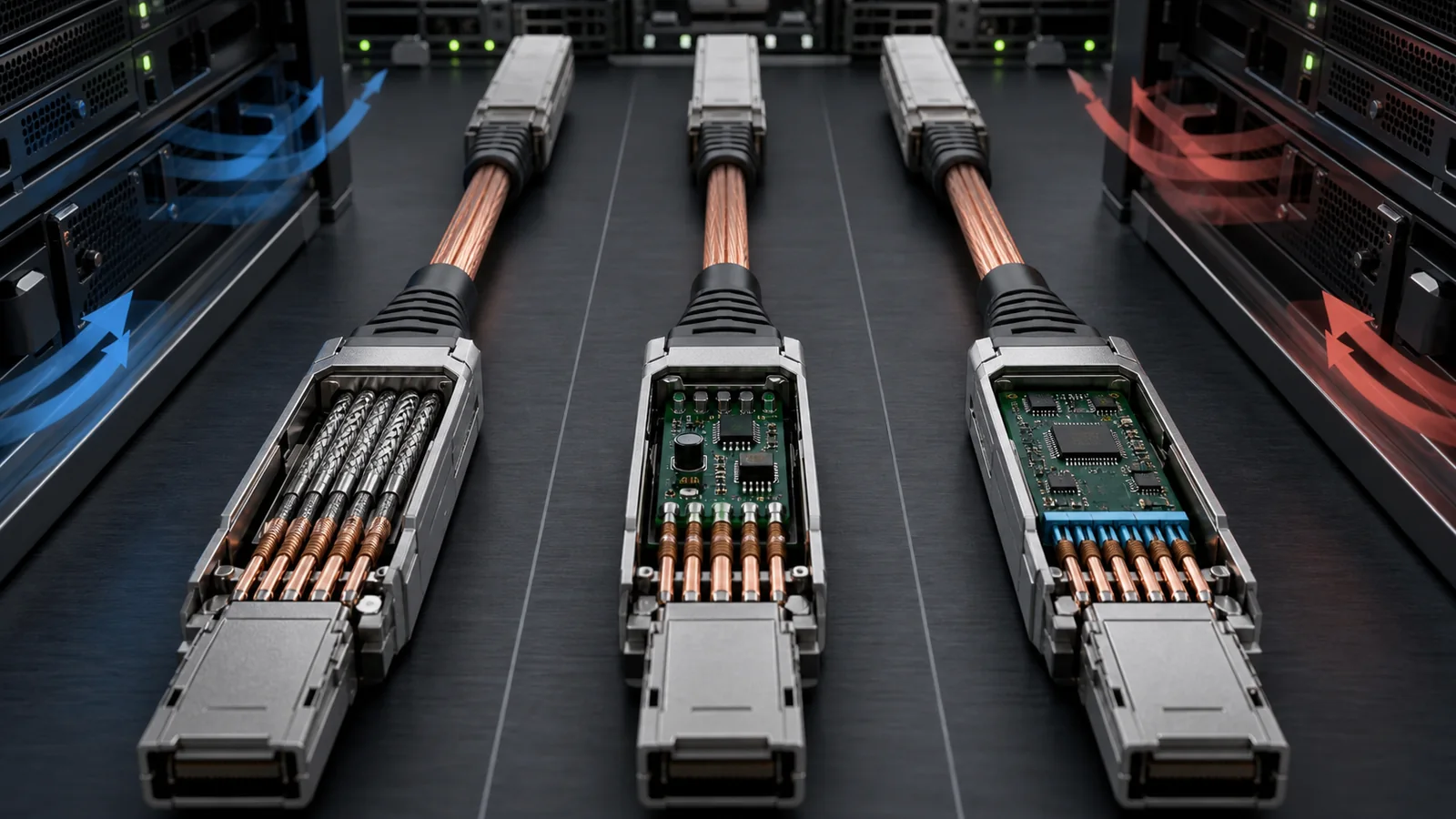
High-speed copper cable labels are easy to compress into a price table and difficult to recover from after an installation fails. A passive DAC, a linear active copper cable and a DSP-based active electrical cable may use the same mechanical connector and advertise the same aggregate rate. Internally, however, they assign signal-conditioning work to different places. That changes reach, power, heat, latency, host dependence, diagnostics and the evidence needed for approval.
The most important buying rule is to request an architecture declaration rather than trusting the acronym alone. DAC normally means a passive direct-attach copper assembly. ACC often means an active copper cable using analog or linear signal conditioning. AEC commonly refers to an active electrical cable using retiming or digital signal processing. Vendor language is not fully uniform: some suppliers use ACC as a broad category that includes different electronics, and others use active copper without stating whether the design is linear or retimed. The supplier must disclose what is inside the cable ends.
This article assumes the project has already selected copper as the medium. If the open question is copper versus optical fiber, start with the AOC versus DAC guide. Here the decision is narrower: which copper architecture can meet the named endpoints, route and operating model without shifting hidden risk into the host or cable assembly?
Quick comparison
| Decision factor | Passive DAC | Linear ACC / LACC | DSP-based AEC |
|---|---|---|---|
| Electronics in cable end | Identification and passive conductors; no active signal retimer | Analog amplification, equalization or pre-emphasis, implementation dependent | Retiming or digital signal-processing functions, implementation dependent |
| Typical role | Shortest, lowest-power copper links | Extend copper reach with modest active conditioning | Extend or stabilize an electrical link through stronger signal regeneration |
| Port power | Very low or effectively passive apart from identification circuitry | Higher than DAC | Usually higher than DAC and often higher than linear ACC |
| Latency | Minimal cable contribution | Typically low, but must be documented | Includes processing/retiming contribution; obtain measured or specified data |
| Host-channel dependence | High; the host must close the complete passive channel | Still host-dependent; linear electronics do not create a protocol-independent tunnel | Retiming can change the channel boundary, but host mode and firmware remain relevant |
| Diagnostics and management | Usually limited | Vendor-specific | May expose richer management, but never assume without a memory-map declaration |
| Main procurement risk | Ordering too long or too thin a cable for the host channel | Treating all ACCs as equivalent or assuming analog conditioning guarantees interoperability | Treating a DSP cable as universally transparent to every host and port mode |
The table describes common architecture patterns, not fixed definitions across every supplier. Exact cable data sheets and host documentation control the purchase.
Passive DAC: the complete electrical channel remains with the hosts
A DAC is a fixed assembly of shielded twinax conductors and pluggable cable ends. It does not convert the signal to light. The host SerDes, board traces, connector, cable conductors and far-end host together form the high-speed electrical channel. Cable length, conductor gauge, shielding, insertion loss and crosstalk therefore matter directly to link closure.
Passive copper is attractive because it can deliver low power, low latency and low component count over short distances. It is also unforgiving of casual substitution. A host may qualify a specific cable length and gauge while rejecting another assembly that looks mechanically identical. The endpoint form factors must match, but mechanical fit alone proves very little about electrical performance.
For a DAC purchase, record:
- exact connector at each end;
- aggregate rate and lane rate;
- straight or breakout topology;
- host port mode and FEC;
- cable length measured along the actual route;
- conductor gauge and outer diameter;
- minimum bend radius and service-loop policy;
- cable part number and revision;
- host support or tested-combination evidence.
Avoid the habit of ordering the longest available DAC "for flexibility." Longer copper can increase insertion loss and cable bulk. Excess length stored behind a switch can obstruct airflow or violate bend limits. Measure the route and order the controlled length.
Linear ACC: active analog help without a retiming boundary
A linear active copper cable adds analog signal-conditioning electronics in one or both cable ends. NVIDIA calls its current implementation LACC and describes linear amplification or pre-emphasis rather than a DSP. That detail is vendor-specific but illustrates the architecture: the cable can compensate for part of the electrical loss while keeping latency and power lower than a more complex retimed design.
Linear conditioning does not make the end-to-end channel independent of the host. The switch or adapter SerDes still interacts with the cable, connector and far-end receiver. Equalization range, gain, noise, lane rate and host tuning remain important. A linear ACC qualified on one platform cannot automatically be transferred to another platform simply because the connector and aggregate speed match.
Buyers should ask which functions are implemented and where. Does the cable provide transmit pre-emphasis, receive equalization, continuous-time linear equalization, automatic adaptation or fixed settings? Is the conditioning symmetrical? Does it support the requested breakout mode? How does the host identify it? What power does each end draw, and what case temperature applies at the stated ambient?
NVIDIA's documentation provides useful examples of LACC in named product families and lengths, but those figures must not be generalized to every ACC. The correct rule is to keep each power, reach and latency statement attached to its cable family and test condition.
DSP-based AEC: a stronger boundary with additional operational questions
An active electrical cable commonly called AEC may use retimers or DSPs to recover, process and retransmit high-speed electrical data. This can allow a longer or more challenging connection than a passive assembly, but it creates active endpoints that consume power, generate heat and may have firmware, initialization and management behavior.
The word "retimed" is not enough. Confirm whether the cable supports the exact electrical interface, lane rate, modulation, FEC relationship, breakout and protocol required by both hosts. Some devices are built for a specific Ethernet environment; others target a particular switch-to-adapter topology. AEC is not a universal electrical adapter.
Ask for the cable's startup behavior and fault model. If one end loses power or a lane degrades, what does each host report? Can both cable ends be read through the module-management interface? Are temperature, voltage, firmware revision and lane status visible? Can firmware be updated, and if so, who owns version control? Is there a recovery path after a failed update? These questions may not exist for a passive DAC, but they matter for an active assembly deployed at scale.
Latency should be handled with the same discipline. Reject absolute claims that a cable adds no delay. Request a maximum or measured contribution with test conditions and clarify whether the figure is one-way, round-trip or an estimate. For many data-center links the difference may be operationally acceptable, but the decision must be evidence-based.
The route determines more than length
The cable route influences all three architectures. Record rack units, vertical and horizontal managers, entry direction, bend points, service loop, airflow zones and the need to remove neighboring equipment. A cable that passes on a bench may be unsuitable when bent sharply behind a dense switch or pressed against a hot exhaust zone.
Passive DACs can become thick at longer lengths or lower gauges. Linear ACC and AEC designs may use thinner conductors because electronics compensate for loss, but the active connector housings still need thermal clearance. Compare actual outer diameter, connector envelope, pull-tab accessibility and bend radius rather than generic category claims.
Do not estimate route length as straight-line rack distance. Follow the installed path and include vertical travel, managers and service allowance. Too short creates connector strain; too long creates coils that can obstruct airflow and confuse operations.
Endpoint and port-mode qualification
Create a port-to-port map before requesting quotes. The minimum fields are source device, source port, destination device, destination port, protocol, aggregate rate, lane or breakout mode, connector at each end, route length and approved cable family.
For breakout cables, treat every branch as a separate logical link. Record branch labeling, far-end form factor and lane group. A 1:2 or 1:4 cable is not defined by branch count alone. The host must support that channelization, and the active cable electronics must implement the corresponding lane map.
Confirm auto-negotiation and FEC expectations. A cable can be electrically capable while the hosts disagree on port configuration. Record what was requested and what became active. If the host provides cable or module identification, save the raw output so a later lot can be compared.
Host qualification can come from several levels of evidence:
- platform-vendor support list naming the cable;
- cable-vendor report for the exact host and software;
- customer sample test on the exact endpoints;
- analogy to a similar platform;
- mechanical fit only.
Only the first three can support an approval, and they are not identical. State the evidence level rather than collapsing them into "compatible."
Power and thermal planning
Power estimates must be per cable end and tied to operating mode. A breakout cable may have different consumption at the high-rate and branch ends. Multiply by port population and include the chassis airflow direction, ambient inlet temperature and neighboring modules.
Passive DAC usually has the lowest active power burden. Linear ACC adds analog electronics; AEC adds more complex active processing. That sequence is directionally useful but not a substitute for the exact specification. A well-designed AEC can be acceptable in a host with sufficient cage power and cooling, while a lower-power cable can still overheat if airflow is blocked.
During sample validation, log module or cable-end temperature after warm-up under sustained traffic. Note whether the reported value is an internal sensor, case temperature or host estimate. Test at realistic port density rather than one isolated cable if the deployment will populate an entire row.
Diagnostics and failure isolation
The simplest architecture is not always the simplest incident. With a passive DAC, faults can originate in either host channel, connector or cable. Swapping against a known-good cable and port is often efficient. With active cables, additional telemetry may help, but the electronics add their own failure and firmware states.
Define the incident workflow before purchase:
- capture both endpoint configurations and counters;
- read cable identity, revision and temperature where available;
- inspect seating, latch, strain and bend condition;
- move the cable to a controlled known-good port pair;
- compare with an approved reference cable of the same topology;
- preserve the failed assembly and raw outputs for supplier analysis;
- do not update firmware or clear evidence before the initial capture.
An RMA agreement should specify whether the supplier can analyze both cable ends, return a root-cause record and distinguish no-fault-found from reproduced failure. For AEC, include firmware and configuration in the traceability record.
Sample-validation matrix
Test the cable as a system, not as packaging. A practical matrix includes:
- exact host pair and software release;
- required aggregate and breakout modes;
- multiple physical ports or port groups;
- planned cable length and one boundary length where relevant;
- cold boot, warm reboot, cable reinsert and port flap;
- sustained bidirectional traffic;
- corrected and uncorrectable FEC counters;
- link-down events and recovery time;
- cable-end temperature and host alarms;
- one controlled route with the intended bends and airflow;
- comparison with a known-good approved cable;
- repeat after a planned host software update if rollout timing requires it.
Do not use one clean ping test as proof. High-speed channels can link while operating with poor margin. Trend error indicators over a defined interval and save the counter-clearing method.
Commercial comparison
Unit price is only one line. Compare:
- cable price by exact length and topology;
- port power and cooling impact;
- installation density and route labor;
- number and type of spares;
- host qualification cost;
- firmware-management burden for active designs;
- failure-analysis capability and turnaround;
- change-notification and revision-control terms;
- risk of replacing one cable class with another during shortage.
A passive DAC may be best within a rack when the route is short and approved. A linear ACC may extend a controlled copper design with low additional latency. A DSP-based AEC may be justified where the stronger signal-conditioning boundary solves a named channel problem. None should be selected because its acronym appears newer.
RFQ checklist
Send suppliers the same controlled record:
- exact End A and End B models, revisions and software;
- port numbers, aggregate rate, lane rate and breakout;
- protocol and required FEC;
- connector at each end;
- measured route and ordered length;
- minimum bend radius, diameter and airflow constraints;
- required architecture: passive, linear active or retimed/DSP;
- maximum power per end and thermal envelope;
- identification, telemetry and firmware requirements;
- host-support and test-evidence expectations;
- lot traceability, process-change notice and RMA terms;
- quantities, spare ratio and delivery schedule.
Require the supplier to mark every exception. If the proposed cable architecture differs, it should be evaluated as a new candidate rather than silently substituted.
Decision summary
Use passive DAC for the shortest approved electrical channel when low power and simplicity dominate. Use linear ACC when the named hosts support the design and modest active conditioning closes a longer copper route. Use DSP-based AEC when a retimed architecture is justified by the channel and the project can manage power, firmware and active-cable operations.
For the earlier media decision, see AOC versus DAC. For failure capture, use the RMA triage guide. To review a real link, send the two endpoints, port mode, route length and candidate cable data sheet. PhotonVerge can identify evidence gaps and propose a sample matrix without representing an untested cable as universally compatible.
Primary sources
- NVIDIA LinkX 100G-PAM4 product-line overview - vendor-specific distinctions among DAC and LACC implementations.
- NVIDIA copper DAC and LACC overview - current named-product reach, power and architecture context; figures must not be generalized.
- NVIDIA LinkX 400G user guide - endpoint, breakout and cable-technology examples.
- NVIDIA DGX SuperPOD cable technologies - system-design discussion of passive and active copper tradeoffs.
- NVIDIA NDR component connections - named NDR cable topology examples and endpoint boundaries.