Quick answer
An orderable InfiniBand NDR cable BOM cannot be built from speed and length alone. “400G NDR, 3 m” omits the information that decides whether the assembly can be installed and configured: the source and destination devices, exact ports, logical lane mode, whether a physical OSFP cage carries one or two links, the connector and cooling form at each end, the media type, the measured route, the breakout branch identity, and the manufacturer part number supported for the recorded platform and software release.
The reliable workflow starts with a port-to-port map. Each row is then enriched with physical route data, connector form, protocol and lane mode, media architecture, ordered length, branch labels and evidence references. Only after those fields agree should a buyer ask a supplier to name an exact candidate part number. This sequence prevents a familiar failure: choosing a cable from a familiar connector photograph and discovering later that one end is a twin-port switch cage, the other is a single-port adapter, the requested 200G service needs a different lane split, or the selected part number is documented for another protocol or product generation.
1. A cable BOM is a translation of the network design
The logical network diagram answers who connects to whom. A cable BOM must answer how every one of those logical links becomes a physical, orderable and traceable assembly. Those are different jobs.
The InfiniBand Trade Association announced NDR as a four-lane 400 Gb/s mode and also described a two-lane 200 Gb/s mode. NVIDIA documentation calls the latter NDR200. That lane arithmetic matters because the face of a connector does not tell a buyer how many logical links, lanes or branches the system will use. The same broad speed label can appear in switch-to-switch, switch-to-adapter, switch-to-DPU and breakout contexts, each with a different physical assembly.
Treat the network design as the controlled input. Before selecting media, assign a unique link ID to every intended connection and record:
- the source rack, device, slot and port;
- the destination rack, device, slot and port;
- the required protocol and configured link rate;
- whether the service is native NDR, NDR200, or a documented transition to an older generation;
- the redundancy plane or fabric identity; and
- the design revision that authorized the connection.
This information prevents procurement from silently changing topology. If a quotation merges two rows because their endpoints look similar, the link IDs reveal the difference. If the design changes a destination port, the row can be revised without guessing which unlabeled cable is affected. The cable schedule becomes an engineering record rather than a shopping list.
NVIDIA's Cabling Data Centers Design Guide describes a comparable progression from network connectivity documentation to route measurement, a point-to-point map, a bill of materials, labeling and deployment. That sequence is a vendor best practice for the systems covered by the guide; it should not be represented as an IBTA mandate. It is nevertheless a useful procurement discipline because it keeps logical intent, physical installation and purchased material synchronized.
2. Separate the physical cage from the logical ports
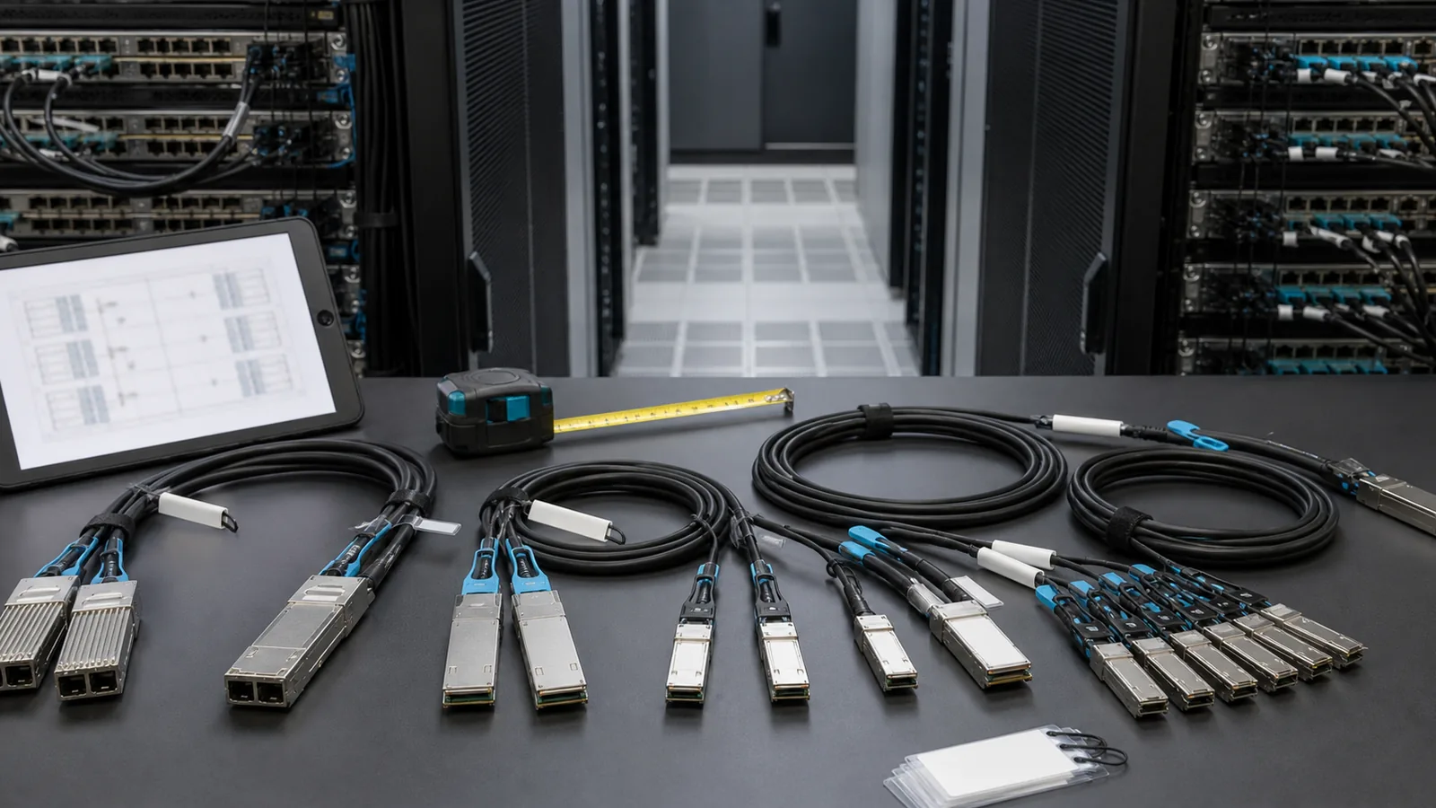
One of the highest-risk NDR purchasing assumptions is that one visible connector equals one logical link. In the NVIDIA Quantum-2 example documented in the NDR components guide, 32 physical OSFP cages provide 64 NDR ports. A finned OSFP connector at the switch can carry two logically independent InfiniBand links. The buyer therefore needs both a physical-cage identifier and the logical port or branch identifiers served by that cage.
The same NVIDIA guide distinguishes several endpoint forms in its covered NDR system:
- a finned, twin-port OSFP form at the documented switch end;
- a flat, single-port OSFP form for the documented adapter connection; and
- a single-port QSFP112 form for the documented DPU connection where card-edge space is limited.
These statements describe the named NVIDIA architecture, not every product marketed as NDR. “Finned,” “flat,” “integrated heat sink,” and “riding heat sink” are not safe substitutes for an exact manufacturer form-factor designation and ordering code. A cable assembly that fits one cage mechanically must not be inferred to fit another cooling arrangement. Likewise, an OSFP-shaped end does not prove the correct protocol, lane allocation, firmware recognition or thermal result.
For each endpoint, the P2P record should therefore have separate fields for:
- physical cage or connector position;
- logical port number;
- connector/form-factor description copied from the current device documentation;
- required cooling or shell variant where the manufacturer distinguishes one; and
- the document revision that supports that description.
This is particularly important when a twin-port switch end fans into two single-port endpoints. The assembly may look like one cable at the switch, but operations will manage two links. Both branches need independent destination identities and labels.
3. Classify every connection before choosing media
Start by placing each P2P row in one of four connection classes. This forces the buyer to select from the correct architecture instead of searching for a generic “NDR cable.”
Switch to switch
In the NVIDIA NDR example, a switch-to-switch copper assembly has a finned OSFP connector at each end and contains two logically independent InfiniBand links. The procurement record must identify both links even when they share the same physical connector and outer assembly. A replacement decision affects the complete assembly, so the spare plan should also recognize that shared failure domain.
Switch to adapter or NIC
The cited NVIDIA design uses a finned twin-port OSFP at the switch end and two flat single-port OSFP ends at the adapter side. A buyer needs two distinct adapter port destinations, a branch ID for each leg, and a clear relationship between the branch labels and the switch's logical ports. “OSFP to OSFP” is not an adequate description because it hides the one-to-two physical arrangement and the different endpoint shells.
Switch to DPU
For the DPU scenario in the same guide, the two branches end in QSFP112 connectors. The reason given is card-edge space. This does not establish that every DPU uses QSFP112 or that every QSFP112 cable supports InfiniBand NDR. Record the exact DPU model, port, software level and the supported cable family before converting this architecture into an order.
NDR to an earlier-generation endpoint
Connections from NDR switches to HDR or EDR are a separate transition case in NVIDIA's documentation. They should not be mixed into a native-NDR BOM through a vague “backward compatible” note. The row must name both generations, the intended port mode, the applicable transition assembly and the source that supports it. A system-level backward-compatibility statement does not make every NDR cable usable with every older endpoint.
The classification step also helps reviewers catch accidental protocol substitution. An Ethernet cable and an InfiniBand cable may share a nominal data rate and a related pluggable shape. That is not evidence that their coding, management, supported part number or host configuration is interchangeable.
4. Record rate and breakout as lane behavior, not marketing shorthand
NDR is documented as four lanes at 100 Gb/s per lane for a 400 Gb/s link. NDR200 uses two such lanes for a 200 Gb/s link. The purchasing consequence is that the aggregate speed printed in a product name does not fully specify how a port will be divided.
For every link, write the expected lane use and breakout ratio in unambiguous terms. Useful values include:
- native NDR: one 400 Gb/s logical link using four 100 Gb/s lanes;
- NDR200: one 200 Gb/s logical link using two 100 Gb/s lanes;
- twin-port switch connection: two separately identified logical links sharing the documented switch-side OSFP assembly; and
- an explicitly documented fan-out in which each branch has its own endpoint and rate.
Avoid using “1:2” or “splitter” without stating what is being split. It may refer to physical connector count, logical port count, aggregate line rate, or an optical fiber mapping. A quotation can appear correct while two parties interpret the ratio differently.
The switch configuration also belongs in the evidence package. A cable cannot create a port mode that the host does not expose. Record the intended switch port profile, adapter or DPU mode, and relevant software or firmware release. Ask the equipment vendor's current documentation to confirm that the requested mode and part-number family are supported together. EEPROM recognition or a readable vendor name is useful identity evidence, but it does not by itself prove that the end-to-end lane configuration will come up or remain supported.
Where a future product description references 1.6T, XDR or 200G-per-lane technology, keep it out of this NDR BOM unless the actual endpoint design requires it. IEEE P802.3dj remains a draft project as of 11 August 2026 and concerns Ethernet, not InfiniBand NDR qualification. An NDR buying guide should not borrow a draft Ethernet compliance statement to make a cable appear more capable.
5. Measure the installed route before assigning an order length
Rack coordinates provide a starting point, not a cable length. The route must follow the actual support path through horizontal and vertical managers, overhead or underfloor containment, rack entry points and service positions. It also needs the slack required by the site's installation and maintenance practice.
For each P2P row, distinguish at least three measurements:
- straight-line or rack-coordinate distance, used only for early planning;
- surveyed pathway distance along the intended installed route; and
- ordered assembly length after applying approved service slack and the available manufacturer length increments.
Do not round all links in a zone to one convenient length without checking congestion and serviceability. Excess length consumes pathway capacity, increases weight and can force tight storage loops. Insufficient length encourages installers to violate bend-radius guidance or pull on the connector. The correct trade-off depends on the exact cable design and the facility's routing standard.
NVIDIA's NDR component guide publishes bend-radius examples for the assemblies in its scope: it distinguishes the connector region from the body of a copper cable and provides a separate value for fiber. Those numbers are not universal limits. Put the candidate manufacturer's minimum bend radius, cable outside diameter, pull limits and connector-clearance requirements in the submittal review. The most restrictive applicable requirement should govern the planned route.
The route record should also note obstructions and maintenance access. A finned switch connector, a dense adjacent port population or a branch point may require more working clearance than a plan view suggests. A technically correct length can still be operationally poor if the pull tab cannot be reached or one replacement disturbs several live neighbors.
6. Choose the media architecture for the documented route
Media selection should happen after endpoint classification and route measurement. In NVIDIA's NDR connection guide, passive direct-attach copper and active copper are mainly used inside a rack or between adjacent racks. Passive DAC is described as requiring no port power in that guide, while ACC uses electronics and draws port power to extend reach. Those are useful architectural distinctions, but the guide's approximate power and distance examples apply to its covered assemblies, not to every product from every supplier.
For longer NDR routes, the guide describes separable optical transceivers with passive MPO/APC fiber. It distinguishes single-mode and multimode options, native links and split configurations. The optical architecture changes the service model: a damaged trunk may be replaced separately from a transceiver, and a transceiver failure does not necessarily require replacing the installed fiber. It also adds interfaces that must be inspected, cleaned and included in the loss and maintenance plan.
Avoid universal statements such as “DAC is always cheapest,” “ACC is always lower latency,” or “optics are always better for airflow.” A defensible BOM records the candidate assembly's published power, dimensions and reach and evaluates them against the host and route. Commercial comparisons require current quotations, spare strategy, installation labor and the cost of changing a fixed assembly; a media label alone does not provide total cost.
The NVIDIA NDR overview says AOC is not practical for its native NDR architecture and directs longer links toward transceivers plus passive MPO fiber. Elsewhere, vendor portfolios may include active optical assemblies for particular transition or Ethernet scenarios. Write the BOM against the exact platform documentation rather than turning one architecture's design choice into the claim that InfiniBand can never use an AOC.
7. Treat MPO/APC, fiber type and branch mapping as separate fields
The NDR components guide identifies MPO/APC for the optical connections it covers and says those assemblies do not interoperate with the older InfiniBand MPO cables used for HDR or EDR. That is a meaningful procurement boundary. “MPO” alone is incomplete.
An optical P2P row should state:
- connector family and end-face style at each end;
- single-mode or multimode fiber;
- fiber count and assembly construction;
- straight or fan-out topology;
- branch labels and destination mapping;
- transceiver family at both ends; and
- the documented reach for that exact transceiver and fiber combination.
Do not infer interchangeability from equal fiber counts. MPO/APC and MPO/UPC must not be treated as alternative spellings, and single-mode and multimode transceivers are not interchangeable. A breakout assembly also needs a verified lane map; a correct connector can still deliver the wrong transmit/receive or branch relationship.
This article intentionally does not reproduce polarity methods or generic MPO inspection criteria, which belong in separate resources. The BOM-level requirement is simpler: preserve the complete connector, fiber and branch designation from the approved architecture, and demand a traceable assembly drawing or manufacturer data sheet that shows the same mapping.
8. Use evidence gates before accepting an exact part number
A supplier suggestion should move through evidence gates rather than directly into the purchase order.
Gate 1: endpoint authority
Confirm the exact device, card, port and software or firmware release at both ends. Save the current manufacturer support page or compatibility matrix reference with an access date. A generic family page is not enough if support varies by hardware revision.
Gate 2: protocol, rate and lane mode
Confirm that the candidate is documented for InfiniBand and for the requested NDR or NDR200 mode. A 400G Ethernet description, a connector photo or an electrical-lane count does not prove InfiniBand support. Record any required port configuration.
Gate 3: physical and cooling form
Confirm the connector shell, cage, latch, heat-sink arrangement, clearance and airflow direction expected by each endpoint. Do not assume that two order-code suffixes are interchangeable because the optical or electrical function appears similar. Manufacturer designations such as integrated or riding heat sink must be tied to the exact platform documentation.
Gate 4: topology and branch identity
Match straight, twin-port, fan-out and splitter construction to the P2P row. Require a branch drawing where more than one logical link shares an end. Verify that each branch label maps to the intended host port.
Gate 5: distance and installation limits
Compare the surveyed route and service slack with an offered standard length. Check bend radius, outer diameter, pull force, connector clearance and environmental rating from the candidate data sheet. “Up to” reach is not an instruction to order that length without a route review.
Gate 6: part-number provenance and lifecycle
Record the equipment manufacturer's orderable part number, any legacy model identifier, the supplier's own SKU and the candidate revision in separate fields. Do not combine them into one synthetic model string. A historical release note may prove that a part number existed at a specific date, but it does not prove current general availability, stock or support. The current product page, platform matrix and quotation should agree.
Gate 7: acceptance evidence
Define what the buyer will retain before production approval: label and EEPROM identity where available, host recognition, configured rate and lane mode, link state, error-counter observations under an agreed workload and duration, and photos of installed routing and branch labels. These are requested acceptance records, not claims that PhotonVerge has already performed or passed a named vendor's qualification.
9. Build a controlled BOM, not a free-text description
A practical NDR cable schedule can use the following columns:
| Field | What it controls |
|---|---|
| Link ID and fabric plane | Unique engineering identity and redundancy context |
| Source rack, device, slot, physical cage, logical port | Exact first endpoint |
| Destination rack, device, slot, physical cage, logical port | Exact second endpoint |
| Protocol and rate | InfiniBand NDR, NDR200 or a documented transition |
| Lane mode and breakout ratio | Logical use of the physical assembly |
| Connector/form at end A and end B | Finned, flat, QSFP112 or another documented form |
| Media and fiber detail | DAC, ACC, or optical architecture; SM/MM and connector finish |
| Surveyed route | Physical pathway distance |
| Ordered length | Approved catalog length including service slack |
| Branch ID and mapping | Traceability for twin or fan-out assemblies |
| Approved manufacturer PN | Exact evidence-backed order code |
| Supplier SKU | Commercial cross-reference, kept separate from the OEM PN |
| Evidence source and revision | Support matrix, data sheet and access date |
| Label text | Installation and operations identity |
| Quantity, spare class and change status | Procurement and lifecycle control |
Use controlled values wherever possible. For example, protocol should not alternate between “IB,” “InfiniBand,” “NDR fabric” and “400G” in different rows. Connector forms should come from a maintained vocabulary tied to the platform documents. Free text can hold exceptions, but it should not carry the fields that decide compatibility.
Version the schedule. When a port, route or approved part number changes, revise the affected row and retain the reason. A supplier's substitute should be a proposed revision with its own evidence, not an undocumented replacement made because the speed and length appear equal.
10. A hypothetical row shows why every field matters
Consider a purely hypothetical connection from a documented NDR switch to two adapter ports. The logical design calls for two independent 400 Gb/s NDR links. The surveyed paths to the adapters are slightly different because the branches enter separate vertical managers.
An incomplete BOM might say:
800G OSFP splitter cable, 3 m, quantity 12.
That wording is unsafe. “800G” could describe aggregate electrical capacity, the shared switch end or a different protocol generation. “Splitter” does not name the branch rate. Both endpoint shells are missing, and one length has been assigned to two routes without showing how it was measured.
A controlled record would instead create two linked branch rows under one assembly ID. It would identify the switch cage and its two logical NDR ports, each destination adapter and port, the documented finned switch-side form, the documented flat adapter-side forms, two 400 Gb/s NDR branches, each surveyed route, the selected order length, branch A/B labels, and an exact manufacturer part number supported for the recorded hardware and software. The supplier SKU would occupy a separate column. The evidence cells would point to the current platform matrix and candidate data sheet.
This example deliberately contains no real order code and makes no compatibility claim. Its purpose is to demonstrate that the topology, not the marketing name, determines the line item.
11. Plan spares around the assembly's failure domain
A shared connector or fixed fan-out changes the operational impact of a failure. Replacing one twin-port copper assembly may interrupt two logical links. Replacing a single pluggable transceiver in a separable optical architecture may leave the trunk in place, but only if the fault has been isolated and the replacement is approved for the exact port and fiber design.
Classify spares by architecture and endpoint form, not only by length. At minimum, distinguish:
- straight twin-port switch-to-switch assemblies;
- finned-to-flat adapter fan-outs;
- finned-to-QSFP112 DPU fan-outs;
- NDR200-specific branches;
- approved legacy-transition assemblies; and
- optical transceivers and passive MPO/APC trunks or splitters.
Record which production rows each spare can replace according to current evidence. Do not call a spare “universal” merely because it has the same visible connectors. If firmware, platform support or lifecycle status changes, revalidate the spare mapping before relying on it during an outage.
Labels should expose the shared failure domain. A common assembly ID plus distinct branch IDs makes it clear that two links are physically coupled. This also helps installers avoid moving the wrong branch and enables operations teams to associate an observed port event with the correct physical path.
12. Keep the BOM valid through review and change control
The BOM is not finished when the purchase order is issued. Before installation, compare delivered labels, part numbers, connector forms, lengths and branch markings with the approved schedule. Quarantine substitutions or unexplained revisions until their evidence is reviewed. Do not force a connector that does not seat normally.
During deployment, record the installed route and any deviation from the surveyed path. Update the label schedule if a port or branch changes. Preserve the final as-built P2P map, because later capacity planning and incident response depend on the physical truth, not the original drawing.
After a firmware or platform change, review the support evidence for affected part-number families. A historical compatibility matrix remains useful provenance but is not proof of present support. Likewise, a current lifecycle label does not prove that a particular cable was accepted in the recorded endpoint combination.
For sourcing discussions, send the controlled rows rather than a screenshot of a product card. Ask the supplier to return the same table with the proposed manufacturer part number, supplier SKU, revision, data-sheet link, supported endpoints, declared media and length, and any unresolved assumptions. A blank evidence field is safer than an invented answer: it identifies what must be confirmed before ordering.
Use the compatibility evidence checklist to structure endpoint and source records, the MTP/MPO polarity guide when a passive parallel-fiber path is involved, and the sample validation plan to define acceptance before candidate assemblies arrive. Each resource owns a separate decision; none replaces the controlled port map.
Send a port map for a bounded BOM review
Submit the approved source and destination ports, hardware and software revisions, NDR or NDR200 lane mode, measured pathways, connector/cooling forms, branch IDs, installation constraints, quantity and available support documents. WUHAN SUNFULL can return a candidate BOM with unresolved fields marked for closure; it will not convert missing platform evidence into a compatibility promise. Send the controlled rows for review.
Conclusion
The best NDR cable BOM begins with endpoints and logical links, not with cable names. It separates physical cages from logical ports, records NDR versus NDR200 lane use, classifies switch, adapter, DPU and legacy-transition connections, measures the installed route, and names the exact connector and media architecture at both ends. It also preserves manufacturer part numbers, supplier SKUs and evidence revisions as different fields.
That discipline does more than prevent a wrong connector from arriving. It creates a traceable chain from network intent to quotation, installation, acceptance records, spares and future changes. For a buyer, that chain is the practical meaning of an evidence-gated BOM.
Primary sources
- InfiniBand Trade Association, InfiniBand Architecture Specification Volume 1 Release 1.5 announcement — 18 August 2021; NDR four-lane 400 Gb/s and two-lane 200 Gb/s context.
- NVIDIA DGX SuperPOD: Cabling Data Centers Design Guide — document DU-10438-001 V04; published 31 March 2023; web edition reviewed as updated 19 November 2025.
- NVIDIA, Document Network Connectivity — P2P mapping, route, BOM and labeling workflow.
- NVIDIA, NDR Overview — NDR/NDR200 lane context and media architecture, updated 19 November 2025.
- NVIDIA, NDR Components — documented switch, adapter, DPU and MPO/APC forms, updated 19 November 2025.
- NVIDIA, Connecting NDR Components Together — documented copper, optical, native and split connection examples, updated 19 November 2025.
- IEEE 802.3 ballot and Task Force review announcements — live status checked 11 August 2026; P802.3dj was in Draft 3.2 second Standards Association recirculation ballot.